Resultant Force Of Distributed Load On Beam
The above beam deflection and resultant force calculator is based on the provided equations and does not account for all mathematical and beam theory limitations. Whole beam is in equilibrium the resultant force to the right of AA must be F downwards.
Engr Help
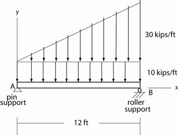
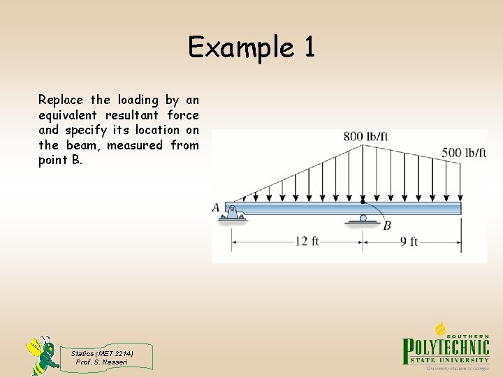
Calculate the magnitude and position of the resultant load.

Resultant force of distributed load on beam. 1 lbfft 12 lbfin. At the free end the shear should go to zero. If there is a distributed load the change in shear is the area under the loading.
So here it would be the load intensity time the beam length. The total magnitude of this load is the area under the loading diagram. 1 Nmm 1000 Nm.
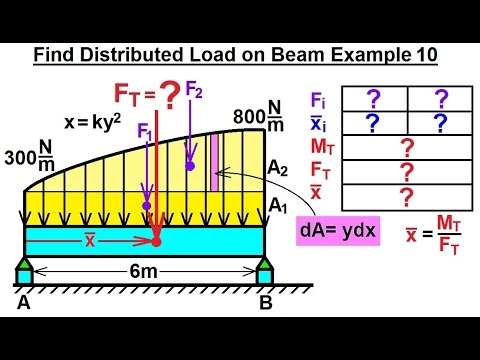
The force magnitude dF acting on it is given as dF wx dx The net force on the beam is given by F R L dF L wx dx A Here A is the area under the loading curve wx. Sketch the beam diagrams and determine the shear force and the bending moment at a section 50 ft from the. The beam carries a concentrated load of 90 kips 12 ft from the right end and a uniform distributed load of 12 kipsft over a 40 ft section from the left end.
P-238 supports a load which varies an intensity of 220 Nm to 890 Nm. Uniformly distributed load is one which is spread uniformly over beam so that each unit of length is loaded with same amount of load and are denoted by Newtonmetre. This load has the same intensity along its application.
These consist of a summation of forces in the vertical direction and a summation of moments. First consider a simple example. NoteThe buoyancy forceis the resultant of all these distributed forces acting on the body.
The intensity is given in terms of ForceLength 7 Distrubuted Loads Monday November 5 2012 Distributed Loads. At the right support the reaction is treated just like the loads of step 4. 1 ft 12 in.
MAGNITUDE OF RESULTANT FORCE Consider an element of length dx. The two distributed loads are inch 10 lbperin 12 lb 120 each. Moments are given as Force x Distance and in this case the force is that exerted by the half of the original beam load W2 x half the length of the beam L2.
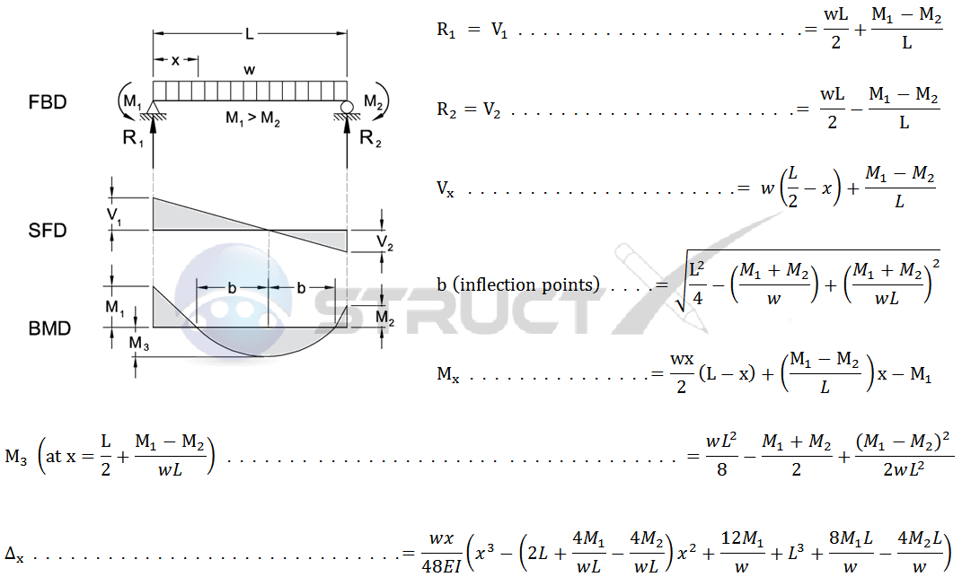
AMERICAN WOOD COUNCIL w R V V 2 2 Shear M max Moment x 7-36 A ab c x R 1 R 2 V 1 V 2 Shear a R 1 w M max Moment wb 7-36 B Figure 1 Simple BeamUniformly Distributed Load. The total downward force is. Recall the buoyancy force is equal to the weight of the water displaced.
Begin equation W 2 times lb 120 2 times lb 100 lb 150 lb 590 end equation Since the beam and loading are symmetrical supports B and F share the load equally so. If a beam has two reaction loads supplied by the supports as in the case of a cantilever beam or a beam simply supported at two points the reaction loads may be found by the equilibrium equations and the beam is statically determinate. This can be expressed as Load x Span divided by 4 as shown.
12 lbfft 1 lbfin. F is called the Shearing Force. 1 Nm 1000 Nmm.
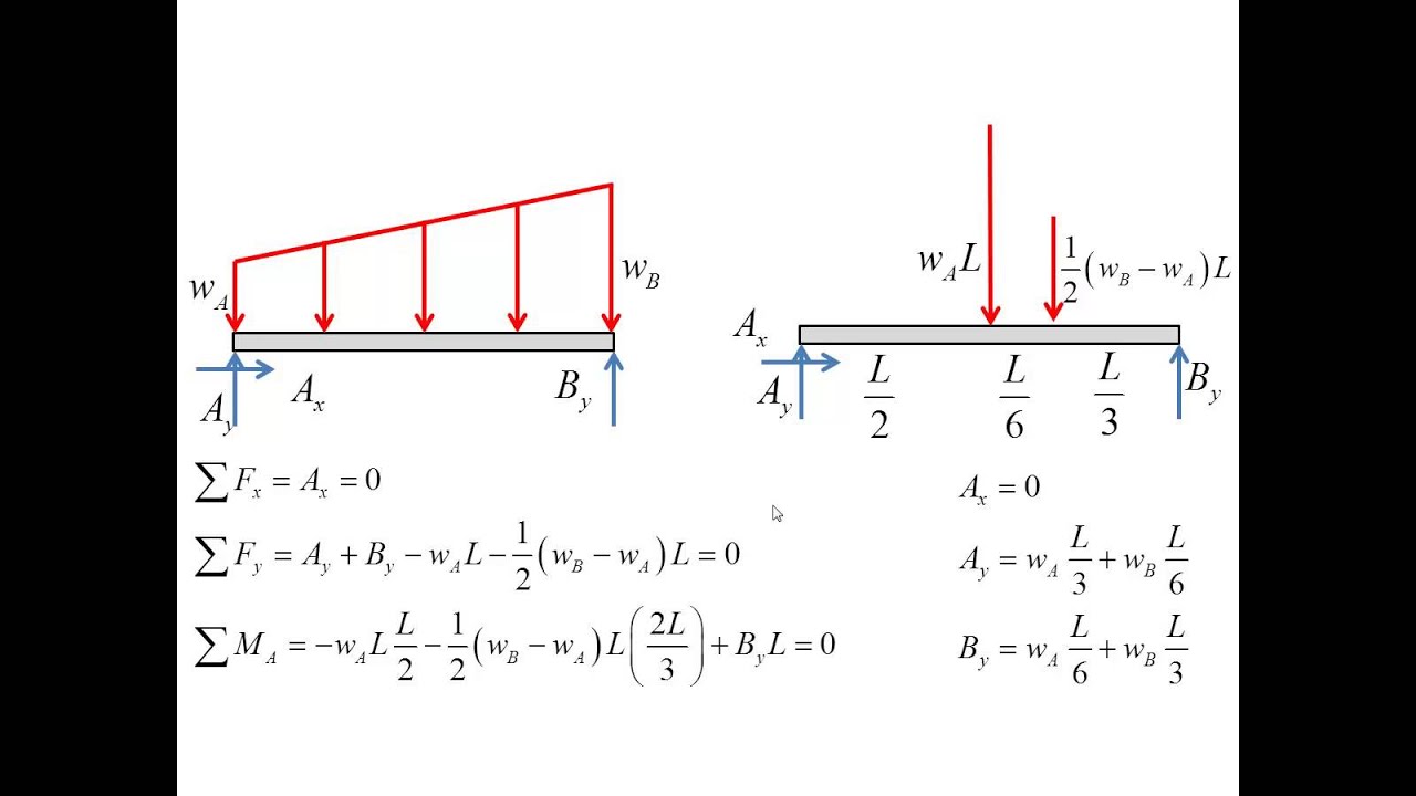
The location of the force resultant is always the center point centroid of the distributed load. Beam Structures and Internal Forces. For a triangular line load it can be shown that the force resultant is one half of the peak value of the distributed load multiplied by the distance over which it acts.
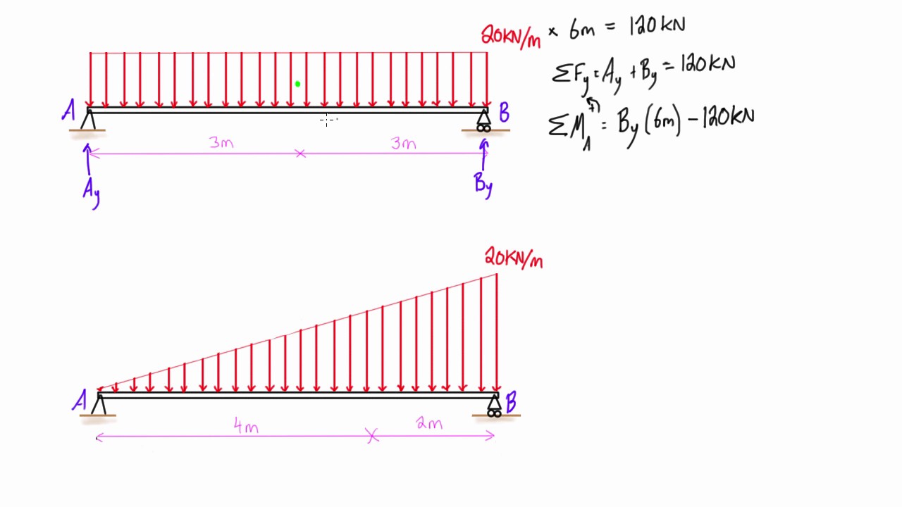
Example calculation of determining the resultant of uniform triangular and trapezoidal beam loads. 1 m 1000 mm. We will apply a uniform load to a beamthat is 3 m long and the space abetween the wall and the beginning of the applied load is 05 m.
The shearing force is defined as the force transverse to the beam at any given section tending to cause it to shear at that section. Distributed load the location of the resultant force is 13 of the length of the load from the larger end 5 kNm 4 m 4 m x m x x b m m 3 4 4 3 1 0 3 1 0 133 m 10 kN. It should be easy to see that if we want to replace this with a single force it mustbe a 250 N load placed in the middle of the loaded region ie.
At free ends and at simply supported ends the moment will have a zero value. The resultant force to the left of X and the resultant force to the right of X forces or components of forces transverse to the beam constitute a pair of forces tending to shear the beam at this section. The beam AB in Fig.
Http Site Iugaza Edu Ps Malqedra Files Lecture 4 5 Pdf
Forces And Moments Met 2214 Statics Met 2214
Simple Beam Uniformly Distributed Load And Variable End Moments
Http Site Iugaza Edu Ps Malqedra Files Lecture 4 5 Pdf
Mechanical Engineering Distributed Loads On Beams 11 Of 12 Find Distributed Load On Beam Ex 10 Youtube

Pin On Construction Spreadsheets Forms

Vectors Vecteurs Vectores Physics Free Body Diagram On The Slope Plano In Vectores Pinterest Body Diagram Physics And Math
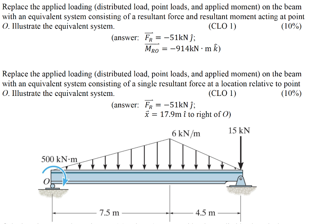
Replace The Applied Loading Distributed Load Point Chegg Com
3d Rigid Body Equilibrium Body Diagram Equilibrium Engineering Mechanics Statics
Statics Ebook Introduction To Distributed Loads


Guardrail Design Based On Aisc Asd And Aci 318 02 Spreadsheet Spreadsheet Engineering Asd

Pin By Bobby Conger On Physics In 2021 Aufbau Principle Planetary Law
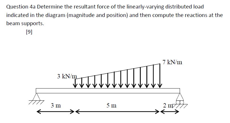
Determine The Resultant Force Of The Linearly Varying Chegg Com
A Beam Under Trapezoidal Distributed Load Youtube
Https Www Kpu Ca Sites Default Files Faculty 20of 20science 20 26 20horticulture Physics Ch4 205 20 20distributed 20loads Pdf
Distributed Loading On A Beam Example 2 Triangular Loads Youtube

Mechanical Engineering Distributed Loads On Beams 4 Of 12 Find Distributed Load On Beam Ex 3 Youtube
Reduction Of A Simple Distributed Loading Engineering Stack Exchange

Tensile Properties Of Textile Fibers Strength Of Materials Fiber Tensile
Post a Comment for "Resultant Force Of Distributed Load On Beam"