Resultant Condition Of Shaft
The net static forces on the shaft at this position should be zero during steady state condition. Solution for general cross sections.
Geometric Tolerancing

We use the solution for a circular shaft as the starting point for our more general solution.
Resultant condition of shaft. The resultant condition iu kin tng hp is the state of a toleranced feature at the other boundary ranh gii the boundary the design engineer believes they care less about. It must be sought for with ardor and attended to with diligence-Abigail Adams Objective of this video is to discuss the. Whereas AME is Actual Mating Envelope.
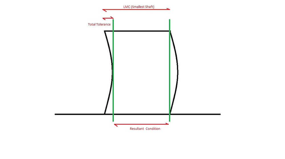
Total Tolerance Bonus Tolerance Geometric Tolerance. SHAFT RC AME - Total Tolerance. Resultant force applied at the grip end of the club into a.
Here is the twist per unit length of the shaft. Resultant Condition Worst case tolerance boundary generated by the cumulative effects of size and geometric tolerance. Determine the resultant internal loadings acting on the cross section at C of the machine shaft shown in Fig.
This is a single tolerance and size event. For each condition the position of the center of mass. A full description of shaft voltage of induction generators in different structures and pulse width modulation techniques have been investigated in 19 20.
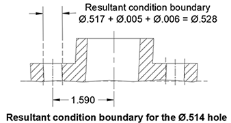
62 03 04 69 mm. As the ends of broken bones are sharp so they may tear or cut the surrounding nerves and blood vessels. This represents the area where any portion of the holes edge may possibly fall.
This resultant condition is not of concern when dealing with assembly of holes and pins. A painful condition namely acute compartment syndrome may occur. 15 0275 m 0125 m 800 Nm0150 m 120 N 0100 m 225 N A y B y b Solution.
Lets us consider a case study for Virtual Resultant condition. In this and earlier versions resultant condition is a variable boundary which is dependent on the produced size of the feature. This outer boundary called resultant condition is calculated as.
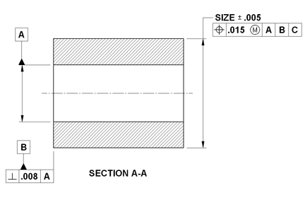
Download PDF - What Are Virtual Resultant Conditions Of Shaft_ Are The Conditions Of The Shaft Will Be Constant Or It Varies Based On The Actual Size_ _ Linkedin wl1p7yz025lj. Obviously the design engineer must be cognizant bit hiu bit bit r of both the MMB and LMB for every feature but in many cases there is one boundary that is more functionally significant. SHAFT VC MMC diameter Position Tolerance Zone Diameter HOLE VC MMC diameter -.
225 N C D 200 mm 100 mm 50 mm 50 mm 800 Nm B a A Fig. The stress field may readily be deduced and resultant torque acting on the ends of the shaft may be computed from the result. The way to calculate resultant condition RC for a shaft and hole is.
In summary the way to calculate virtual condition VC for a shaft and hole is. Learning is not attained by chance. HOLE RC AME Total Tolerance.
The shaft is supported by bearings at A and B which exert only vertical forces on the shaft. The way to calculate resultant condition RC for a shaft and hole is. In this video i have talked about the virtual conditions and resultant condition of the external featurescheck out my part 1 to know more about it.
Resultant Condition-- is the single worst case boundary generated by the collective effect of a feature of the sizes specified MMC or LMC the geometry tolerance for that material condition the size tolerance and the additional geometric tolerance derived from the features departure from its specified material condition. Shaft eccentricity plot shows shaft equilibrium position inside the bearing. For a external feature of size the resultant condition is the variable value and innermost boundary.
The tables in this section provide information about bearing tolerances seat tolerances and resultant fits These should enable you to determine easily the maximum and minimum values of fits when using ISO tolerance classes for bearing seats and bearings with Normal. Femoral shaft fractures may result in further injury and complications which are as follows. For an external feature of size specified at MMC Resultant Condition LMC - Geometric Tolerance allowed.
A high frequency model of AC motor is. As the resultant of the thermal and the mechanical unbalance is not a fixed vector in the shaft. The data from the ADRE was imported to excel sheet to generate a.
LMC stated geo tol any bonus or. Or another way to say it maybe2009 resultant condition can be described as the 1994 maximum resultant condition. Reversed condition would be to place the center of mass at 47 cm in the positive Y direction relative to the axis of the shaft.
Y145-1994 is a little different though. The orientation of the resultant joint force at the wrists was in the direction of motion of the club center of gravity for most. Internal feature of size.
SHAFT RC AME -. For each condition the position of the center of mass.

0053 Calculation For Virtual Condition And Resultant Condition 1st Year Anniversary 3

Mechanical Engineering Basics Virtual Condition Resultant Condition Holes Pins

0053 Calculation For Virtual Condition And Resultant Condition 1st Year Anniversary 3
What Is Resultant Condition Geometric Learning Systems


Mechanical Engineering Basics Virtual Condition Resultant Condition Holes Pins
Gd T Fundamental Rules Vibadirect
What Is Resultant Condition Geometric Learning Systems


Mechanical Engineering Basics Virtual Condition Resultant Condition Holes Pins

Mechanical Engineering Basics Virtual Condition Resultant Condition Holes Pins

Virtual Condition Holes And Pins Youtube

Gdt 2d Virtual Condition

Mechanical Engineering Basics Virtual Condition Resultant Condition Holes Pins

0053 Calculation For Virtual Condition And Resultant Condition 1st Year Anniversary 3

Mechanical Engineering Basics Virtual Condition Resultant Condition Holes Pins

Gdt 2d Virtual Condition
Shaft Diameter Maximum Material Condition Mmc Vs Feature Size Tolerance Chart Tool Calculator Engineers Edge

Gdt 2d Virtual Condition
0053 Calculation For Virtual Condition And Resultant Condition 1st Year Anniversary 3

Mechanical Engineering Basics Virtual Condition Resultant Condition Holes Pins
Post a Comment for "Resultant Condition Of Shaft"